For the first time, I’ve built a fully functional robot with my trusty Raspberry Pi 2. My last attempt at connecting a motor driver to a Pi resulted in a burnt pi; but that was because I connected its 5v output to the driver’s 5v output pin (recipe for disaster).
Rexplorer is the successful result of research preceded by a burnt Raspberry Pi Mod B and an L298N motor driver which blew a fuse.
By the end of this tutorial you will have a fully functional obstacle detecting robot (provided you follow the instructions carefully).
Disclaimer: The author of this tutorial will not be held responsible for any burnt Raspberry Pi(e)s or indirect damage caused to the same due to negligence (as was the case with the author’s).
As you may already know, the Raspberry Pi is a Linux OS computer.
So first, lets take a quick look at the bot (when unplugged from the monitor/screen, keyboard, mouse and any other peripherals).
HARDWARE
- Raspberry Pi – Model B 2 or any 40-pin Pi; you can also use Model B, A+, B+ or Zero if you know their respective pinouts
- Raspberry Pie – Optional, unless you’re hungry
- Motor Driver – Preferably based on L298N
- BO motors – 2 nos.
- Wheels for BO motors – 2 nos.
- Castor wheel – 1 BIG wheel
- Mechanix/Mechano built chassis – You can use any chassis for provided there is space for motors and sensors
- Jumper wires – As many as you can find
- A power bank – Only to power the Raspberry Pi and can be substituted with any decent 5v power supply
- Lithium ion 12v battery pack – To power up the motors.
- Toggle switch – Optional, as it will be used for the power supply to the motor driver
The mouse, keyboard, monitor/screen and other peripherals which are connected to the Pi when it is not running headless (without a display), will now be referred to as the ‘station’.
The HDMI cable connecting the Pi’s display output should be at least one metre long.
The software of PiBot is done in a modified version of the programming language (interface actually) called Scratch. The modified version which we will be using is called Scratch GPIO (version 7).
Scratch GPIO is modelled on Scratch v1.4, but in addition to all the other features, it also gives a user direct access to all of the Pi’s GPIO pins. This makes it easy to program the Pi as a robot with motors, sensors and various other hardware peripherals.
Connect all the hardware as shown in the schematic…
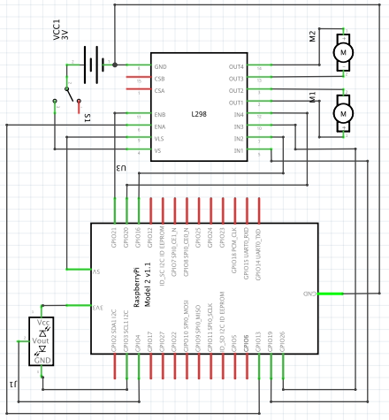
Or as explained here in words…
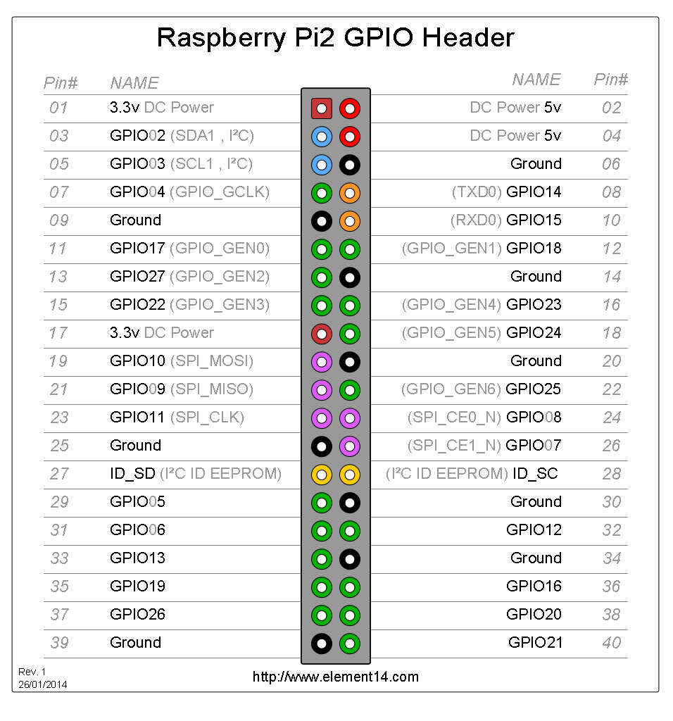
The motor driver’s 2 enable and 4 input pins are connected to pins 31, 32, 35, 36, 37, 38 of the Pi respectively; the motors are directly connected to the driver’s output terminals; the driver’s power supply is connected to the 12v battery (directly or with a toggle switch in between) and the GND/negative wires is also connected to the Pi’s GND (pin 40); the proximity sensor’s VCC is connected to the 3.3v output at pin 1 of the Pi, GND at pin 6, and O/P (output) at pin 7.
Between the two, I think you’ll prefer the schematic 😜
SOFTWARE
Boot the Pi to install Scratch GPIO with an internet connection.
Open the LXterminal and type:
wget http://bit.ly/1wxrqdp -O isgh7.sh
After the installer has been downloaded, type:
sudo bash isgh7.sh
Now that Scratch GPIO 7 and its accessory files are installed, let’s get coding!
Open Scratch GPIO7 (you’ll see a shortcut on the desktop) and drag the following blocks into the blank grey area:

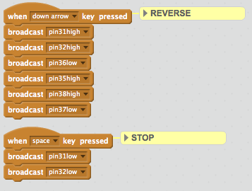
The ‘broadcast’ blocks normally send messages which act as signals in the programme, but in this case they’re actually changing the state of the GPIO pins. The syntax for any output through broadcast is as follows:
pin<pin number><state>
Where ‘pin number’ is the GPIO pin number as per the pinout numbering and ‘state’ is the output at that pin i.e. either high or low.
Test it by clicking on the arrow keys on your Pi’s keyboard and make sure that the pin numbers are correct.
Right now, the robot should move forward, backward, turn left or right depending on the arrow key pressed. This is a quick and easy way to test your motor driver connections and make sure the wires connect the right pins.
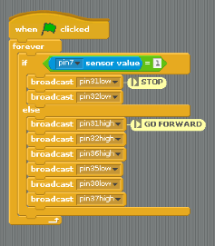
To make it ‘smart’ we need to throw in another script for, let’s say, obstacle detection.
Open the background’s script area by double clicking on its icon near the list of sprites.
Now drag these blocks into the grey area:
Save the project and close ScratchGPIO7.
Lastly, open an LXterminal window and type:
sudo raspi-config
A configuration list should open. Choose option 3 i.e. Enable boot to Desktop/Scratch and at the next list, choose Desktop log in as user ‘pi’ at the Graphical Desktop.
Now reboot your Raspberry Pi and watch the magic unfold!
As soon as the desktop loads, open ScratchGPIO7, open your project (if it isn’t already open) and hit ‘Enter’. The green flag script(s) should start automatically. The motors will now be activated so please check if the Pi is connected and accordingly hold on to it to prevent any untoward incidents.
The Pi can also be accessed wirelessly over SSH (Secure Shell) and VNC (Virtual Network Computing), so you could consider installing RealVNC on the Pi and a laptop/PC to control it (the robot) remotely.
The robot should (as every good obstacle detector does) stop when it detects an obstacle and continue moving otherwise.