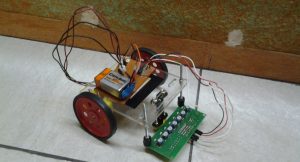
Who said robots need a microcontroller to be smart? This robot certainly doesn’t believe that!
Presenting: LFR Mini! A line follower of the non-programmable kind!

Since LFR Mini has no formal “brain”, it depends almost entirely on the digital line sensor to do the job. However, as you may know, a line sensor works on the principle of reflectance (i.e. dark colours absorb, light colours reflect), and therefore transmits signals based on this logic:
If the colour detected is black
then transmit 0 (negative signal)
If the colour detected is white
then transmit 1 (positive signal)
Hmm… thats good. But only for a white line follower. What if it has to follow a black line?
Fortunately, there is an IC available that can convert signals. e.g. 0 is converted to 1
This IC, popularly known as the NOT Gate, will simply input the negative signal (black) from the sensor and convert it into a positive signal for the motors. Likewise, a positive signal will be converted to a negative signal for the motors.
So far, so good. Just one last challenge to tackle. The 5v signal from the IC, is not enough for the 150 rpm BO motors. The voltage needs to be amplified. So lets throw in a couple of good old NPN transistors. They use 5v from the IC as a trigger and provide an amazing supply of 9v to the motors.
And, just to err on the side of caution, LFR Mini also has a couple of half-wave rectifier diodes to prevent the transistors from back EMF (reverse electromotive force which can cause shorting of parts in a circuit).
Here’s a video of LFR Mini following it’s first line:
The stuff that went into it:
I] The board:
- 7805 IC, 5v Voltage Regulator (1)
- 7404 IC, NOT Gate (1)
- Male header pins (2, for battery)
- Female header pins (4, Two for each motor)
- Male to female wires (2, from battery snap to battery pins & 4, from IC input to sensor output)
- NPN Transistors (2)
- Half-wave rectifier diodes (2)
II] The rest of the robot:
- 150 rpm BO motors (2)
- Wheels for BO motor (2)
- L- brackets for BO motor (2)
- Front caster wheel (1)
- Digital line sensor array (1) (Recommended: RKI-1032 from Robokits) (2 Individual line sensors can also be used as substitutes, but pin connections and power supply outputs on the board have to be modified accordingly.)
- 9v, 200mAh Ni-MH battery (1)
- Custom made acrylic chassis (1)
- Nuts & Bolts of various sizes
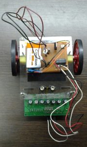
A top view of the final robot:

Credits: Pravin Kakode (krafters.goa@gmail.com) for laser cutting the acrylic chassis.